How to Choose the Right CCS Busbar for Your Project?
Choosing the right CCS Busbar is a pack-design decision, not a catalog comparison. The busbar must connect cells reliably while fitting the available space, current demand, thermal limits, and assembly process. A part that looks suitable on a drawing can still create tight clearances, awkward weld access, or uneven heat distribution in a real battery module. Small details matter.
“Choose for the pack you will build, not just the current rating you need.” This practical design principle captures why electrical performance alone is not enough. I have not attributed it to a named engineer because no verifiable source was provided; assigning it to an expert would risk misrepresenting a real person’s words.
This guide explains how to compare CCS Busbar options using measurable project requirements. It considers conductor material, cross-section, insulation, sensing integration, connection method, and mechanical tolerances. It also highlights checks that are easy to overlook, such as clearance around fasteners and the effect of repeated thermal cycling. There is no universal best choice. A compact design may suit one module, while another needs more spacing or a different connection layout. Treat calculations as a starting point, then confirm the fit with drawings, supplier data, and prototype testing. Some choices may need revision. That is normal engineering, not failure.
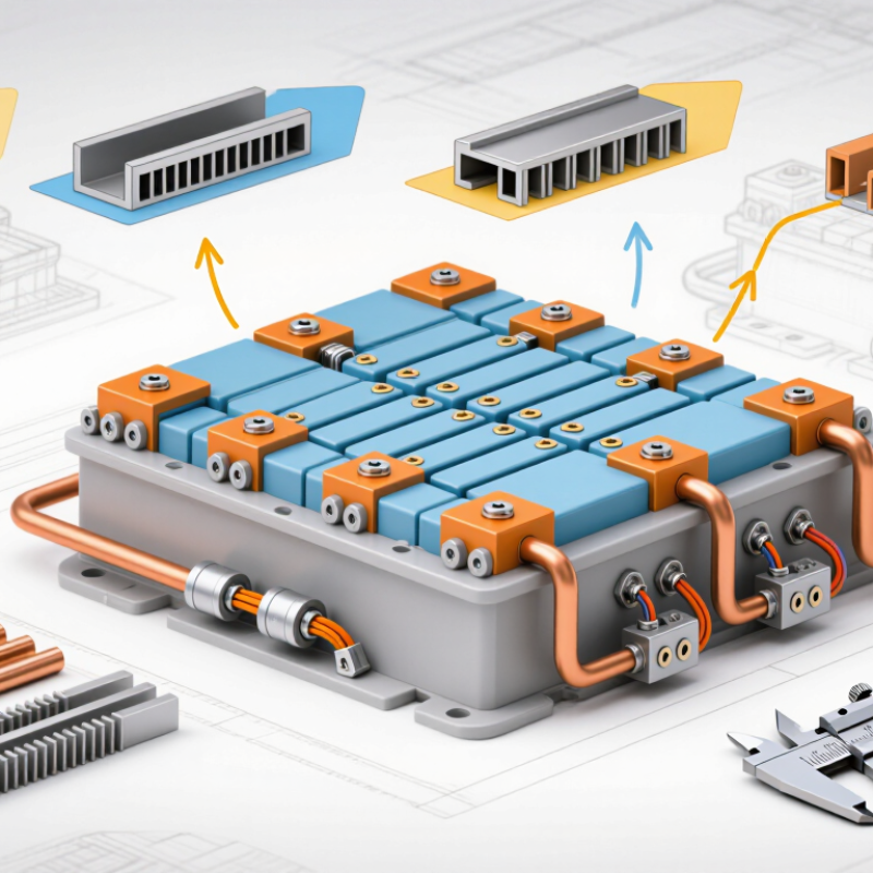
Define the Electrical and Mechanical Requirements of the CCS Busbar
Before selecting a CCS busbar, define the electrical load it must carry. Record continuous current, peak current, operating voltage, and expected duty cycle. Peak demand matters, even when it lasts only seconds. Estimate resistive losses and allowable temperature rise for the actual enclosure, not an open-air test bench. A crowded battery module can trap heat. Check short-circuit conditions and insulation requirements with the system design team.
Mechanical requirements deserve equal attention. Measure cell spacing, terminal positions, available height, and clearance to nearby parts. Allow for manufacturing tolerances; a small mismatch can stress a weld or connector. Consider vibration, thermal expansion, and service access. Will the busbar flex without touching neighboring components? It should not rely on perfect assembly.
Material thickness and geometry affect both resistance and stiffness. Compare options using the same current, temperature, and installation assumptions. Confirm that joining methods suit the cell terminals and production process, then inspect sample assemblies for contact quality and heat concentration. A neat drawing can still mislead. I would verify the fit in a physical mock-up, because cable bends, insulation, and tool access often reveal problems that a model misses. Some details get overlooked. Keep the requirements documented, including test conditions and acceptable limits.
How to Choose the Right CCS Busbar for Your Project?
Define the Electrical and Mechanical Requirements
The chart shows a preliminary area estimate calculated as continuous current ÷ assumed current density of 1.5 A/mm². For example, 500 A ÷ 1.5 A/mm² ≈ 333 mm². This is an illustrative sizing calculation, not a final design recommendation: actual busbar sizing depends on temperature rise, cooling, enclosure conditions, duty cycle, material, and applicable standards. Also define voltage and insulation requirements, connection layout, clearances, mounting points, and available space before selecting a CCS busbar.
Compare Conductor Materials, Thicknesses, and Current Ratings
How to Choose the Right CCS Busbar for Your Project?
In a cell connection system, busbars carry current between cells while fitting tight spaces. The best choice depends on the pack layout, operating current, temperature limits, and connection method. Compare real project conditions, not just catalogue numbers. A busbar that fits neatly may still create a hotspot near a narrow bend.
Copper offers high conductivity and compact designs, but it weighs more and can cost more. Aluminum is lighter, though it usually needs a larger cross-section for similar electrical performance. Some designs combine materials to balance weight, conductivity, and joining needs. Not always. Check how the conductor material interacts with terminals, coatings, and the selected joining process. A small contact area can matter more than expected.
Thickness affects resistance, stiffness, heat flow, and available space. Increasing thickness may reduce resistance, but it does not guarantee a higher safe current rating. Ratings depend on conductor width, length, insulation, ambient temperature, cooling, and allowable temperature rise. Ask for test data that matches your intended conditions, including peak and continuous current. A neat spreadsheet can still mislead. Prototype the busbar in a representative assembly, then measure temperature at joints and narrow sections under load.
How to Choose the Right CCS Busbar for Your Project? — Compare Conductor Materials, Thicknesses, and Current Ratings
| Conductor Material | Representative Strip Size
(Width × Thickness) | Cross-Sectional Area | Typical Electrical Conductivity | Indicative Continuous Current | Key Selection Considerations |
| Unplated copper | 20 mm × 1.0 mm | 20 mm² | Approximately 100% IACS | About 40–80 A | High conductivity and compact size; check corrosion exposure and compatibility with cell terminals. |
| Tin-plated copper | 20 mm × 1.0 mm | 20 mm² | Copper substrate: approximately 100% IACS | About 40–80 A | Plating can improve contact and corrosion behavior. The current capability is governed mainly by the copper section and the finished assembly. |
| Unplated aluminum | 20 mm × 1.0 mm | 20 mm² | Typically about 61% IACS for commercially pure aluminum | About 30–60 A | Lower mass and cost than copper for many designs; account for oxide formation, joint design, and the larger section often needed. |
| Unplated copper | 30 mm × 1.5 mm | 45 mm² | Approximately 100% IACS | About 90–180 A | A practical mid-size option where low resistance and moderate package thickness are priorities. |
| Unplated aluminum | 30 mm × 1.5 mm | 45 mm² | Typically about 61% IACS for commercially pure aluminum | About 70–130 A | Lower conductor mass than copper at the same dimensions; verify terminal interface and thermal performance. |
| Unplated copper | 40 mm × 2.0 mm | 80 mm² | Approximately 100% IACS | About 160–280 A | Offers a larger conducting section for higher-current paths, but adds mass and may require more space and support. |
| Unplated aluminum | 40 mm × 2.0 mm | 80 mm² | Typically about 61% IACS for commercially pure aluminum | About 120–220 A | Can reduce busbar mass relative to copper; confirm that the larger dimensions and connection method suit the CCS layout. |
Important: Current figures are indicative screening ranges, not certified ratings. Actual ampacity depends on busbar length and geometry, cooling, enclosure, ambient temperature, allowable temperature rise, duty cycle, joints, and cell-terminal limits. Validate the complete CCS assembly by thermal and electrical testing against the applicable project requirements.
Assess Battery Layout, Cell Connections, and Insulation Needs
A reliable CCS busbar starts with the real battery layout, not an idealized drawing. Map cell pitch, terminal direction, module boundaries, and service access before fixing conductor geometry. The IEA’s Global EV Outlook 2024 reports that electric-car battery demand reached about 750 GWh in 2023, roughly 40% above 2022. That growth does not dictate one busbar design, but it highlights why repeatable, buildable connections matter. Small details matter. Check whether busbars can be installed without bending cell terminals or blocking inspection.
Match each connection to its current path and mechanical conditions. Record joint type, fastener access, expected temperature, and any movement from vibration or thermal cycling. Allow for movement. Then assess insulation against the system’s maximum operating and transient voltages, not just nominal voltage.
Set clearances and creepage distances for the actual materials, pollution conditions, and altitude, and verify them against applicable standards. A CAD layout can look generous while a molded rib or sharp edge reduces real spacing. That is easy to miss. Prototype the stack-up, inspect tolerances, and perform dielectric testing on representative assemblies before production. Keep sensing wires separated from high-current paths where practical, and make covers removable without stressing the cell connections.
Check Manufacturing Methods, Tolerances, and Assembly Compatibility
Choosing a CCS busbar starts with understanding how it will be made. Stamping suits repeatable production, while laser cutting can help validate a design before tooling is ready. Forming adds another variable: bends may shift contact points slightly. Small details matter. Ask suppliers how they control burrs, flatness, and edge condition, especially near insulation films and weld zones.
Tolerance is not just a number on a drawing. Check critical dimensions against the full assembly stack-up, including cell position, fixtures, and connector features. A hole that looks acceptable alone may misalign after several cells are installed. Define datums clearly, then review inspection methods and sample measurement reports. Avoid demanding extremely tight tolerances everywhere; they can increase cost without improving function. Still, critical contact areas deserve careful control.
Assembly compatibility should be tested with real components, not only CAD models. Confirm that the busbar sits flat, reaches its weld locations, and leaves clearance for nearby parts. Review joining methods, coating or insulation requirements, and access for tools or inspection. A prototype build can reveal issues that drawings miss. It may feel slower, but finding a tight fit before production is usually less disruptive. Some assumptions will still need revision. That is part of the process.
Verify Safety, Thermal Performance, and Applicable Standards
How to Choose the Right CCS Busbar for Your Project?
Verify Safety, Thermal Performance, and Applicable Standards
A CCS busbar can look robust and still overheat at a joint. Check the exact copper-clad steel grade, cross-section, plating, and connection method; “CCS” alone does not define current capacity. Ask for verified resistance and temperature-rise test results. Test the real assembly, including fasteners, insulation, enclosure, and cooling. Small contact areas matter.
The IEA’s Global EV Outlook 2024 reports nearly 14 million electric-car sales in 2023, about 18% of global car sales. That growth makes dependable battery connections important, but it does not establish a safe busbar rating. Use the project’s peak and continuous currents, duty cycle, ambient temperature, and fault conditions. A catalog ampacity is not a design result. It rarely captures your enclosure.
Match standards to the application. IEC 61439-1 provides verification requirements for applicable low-voltage switchgear assemblies, including temperature-rise verification; battery systems may require additional standards, such as IEC 62619 or UL 2580, depending on use and market. Confirm the current edition and scope with the responsible engineer. Then review test records and traceability, not just a certificate image. One caveat: test conditions may differ from yours. That deserves a second look.