What Is a Component Terminal Block and How Does It Work?
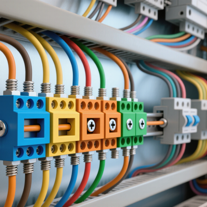
A Component Terminal Block is a compact connection point inside a control cabinet, machine, or electrical panel. It holds conductors in place and connects them to other wires or circuits. Open a cabinet and you may see rows of colored blocks on a DIN rail, with each wire secured by a screw, spring clamp, or push-in mechanism. Small parts. Important work.
The International Energy Agency’s Electricity 2024 report says global electricity demand grew by 2.2% in 2023 and forecasts average annual growth of 3.4% from 2024 to 2026. That report describes the wider electrical-system context, not terminal-block sales. Still, more electrified equipment means more connections that must remain organized, accessible, and dependable. IEA Executive Director Fatih Birol called this shift “the Age of Electricity.” His observation helps explain why even modest connection components deserve careful attention.
In this guide, we’ll look at how a Component Terminal Block works, what its internal conductive parts do, and how insulation helps separate neighboring circuits. We’ll also distinguish common connection styles and explain what to check when selecting a block, including conductor size, current rating, and installation conditions. IEC 60947-7-1 sets requirements for certain terminal blocks used with copper conductors; the relevant product documentation should always be checked. A neat panel is not proof of a sound connection. That is easy to overlook. Reliable performance depends on the right component, correct wiring, and careful verification—not appearance alone.
What a Component Terminal Block Is
A component terminal block is an insulated connector that joins electrical wires or component leads in a circuit. Inside its housing, conductive metal terminals create the electrical path. The outer body helps keep neighboring connections separated. It is not a fuse or switch. Its main job is to provide a stable, accessible connection point.
A wire enters an opening and is held against a metal terminal. Depending on the design, a screw or spring clamp provides the pressure. Some blocks mount on a circuit board; others attach to a panel or support rail. Check the wire size and current rating before selecting one. A loose clamp can cause heat or intermittent operation, while an oversized wire may not seat properly. Small details matter. During installation, gently tug each wire to confirm it is secure, then inspect for exposed strands. The exact arrangement varies, and product drawings can be easy to misread. I would verify the terminal layout before wiring, especially when several circuits sit side by side.
Key Parts and Their Functions
What Is a Component Terminal Block and How Does It Work?
Key Parts and Their Functions
A component terminal block is built from parts that guide, hold, and isolate conductors. The insulating housing supports the assembly and separates adjacent circuits. Inside, a conductive metal bar or plate forms the electrical path. Wire-entry openings direct stripped conductors toward the clamping points. Small openings matter.
A screw, spring, or push-in clamp presses each wire against the metal contact. This pressure creates a reliable connection when wire size and strip length match the block’s specifications. The screw itself is not the current path; the metal contact is. A mounting foot or rail clip holds the block steady on a panel. End barriers and partitions help prevent accidental contact between neighboring terminals.
Marking strips identify circuits, while jumpers can link selected terminals when a shared feed is needed. In a real panel, labels can be overlooked, and a tidy row may still contain a loose wire. After installation, check that no excess bare copper is exposed and verify the specified tightening torque where applicable. Too much force can damage a screw or conductor. That detail is easy to miss.
How Wires Are Secured in the Block
A component terminal block holds an electrical conductor against a conductive metal path, creating a stable connection between wires or circuit components. The wire is usually secured by a screw clamp, spring cage, or push-in mechanism. Each design applies pressure differently, so the conductor must match the block’s specified wire type and size.
For a screw-clamp block, strip only the length shown in its instructions. Too little exposed copper can leave insulation under the clamp; too much can leave bare conductor outside the housing. Insert the wire fully, then tighten the screw to the specified torque. Avoid guessing. Excess force may damage strands or the clamp, while a loose screw can allow the wire to shift. With spring-clamp styles, a small tool may open the cage before insertion. A gentle pull can check that the wire is held, but it does not replace the manufacturer’s installation guidance.
Stranded wire may need a ferrule when the terminal instructions call for one. Never assume every block accepts ferrules or fine-stranded conductors. Power should be isolated before wiring, and no loose strands should remain where they could touch an adjacent terminal. It is easy to rush this step. A careful visual check often catches what a quick tug misses.
How Wires Are Secured in a Component Terminal Block
Different terminal blocks use different actions to clamp a stripped conductor in place.
Illustrative count of typical securing actions after the wire is stripped: insert and tighten a screw clamp; open, insert, and release a lever-operated spring clamp; or insert a wire into a push-in spring clamp. Always follow the terminal block’s instructions for wire preparation and tightening.
How Electrical Current Passes Through It
A component terminal block carries current through a short, clamped metal path. A stripped wire enters the block, and a screw or spring presses it against a conductive contact. Current crosses that contact, travels through the internal metal bus, and leaves through the connected conductor. The insulating housing keeps neighboring circuits separated; it does not carry current. Small details matter. A loose clamp or damaged conductor can raise contact resistance and create heat.
IEC 60947-7-1 sets requirements for terminal blocks used with copper conductors. It is a technical standard, not a performance report for every block, so check the product’s rated current and conductor range. Heat at a contact follows I²R: at 10 amperes, a 0.01-ohm connection dissipates 1 watt locally. That is a calculated example, not a universal terminal-block measurement. The current path may look simple on a diagram, but installation quality changes how reliably it works.
Tips: Strip only the specified wire length, seat every strand fully, and tighten to the stated torque. Then check that the conductor cannot pull free. A quick visual check can miss a poor clamp.