
Stecker Machine Blog

How to Choose a Mechanical Shaft Seal?

A Mechanical Shaft Seal is a small component with an outsized role: it helps contain process fluid where a rotating shaft passes through a pump or other equipment. Selection is not just a matter of matching dimensions. Fluid chemistry, pressure, temperature, shaft speed, solids, and start-stop frequency can all affect seal life. A seal that works well with clean water may struggle with abrasive slurry or a fluid that crystallizes on exposed faces. Small details matter.

The U.S. Department of Energy’s Improving Pumping System Performance sourcebook reports that pumping systems use nearly 20% of global electricity and can account for 25–50% of energy use in some industrial operations. Those figures describe whole pumping systems, not seals alone. Still, they show why leakage, maintenance, and operating efficiency deserve attention together. API Standard 682 also provides established requirements and guidance for mechanical seals in centrifugal and rotary pumps used in petroleum, natural gas, and chemical services. Use the standard alongside equipment data and site conditions—not as a substitute for them. Before choosing a seal, confirm the actual operating range, including upset conditions, and review the available flush or cooling arrangement. Ask how the seal will be inspected and serviced. Simple on paper. Less simple in the plant. Even a careful selection can miss something: field conditions change, and the best choice may need review after startup.
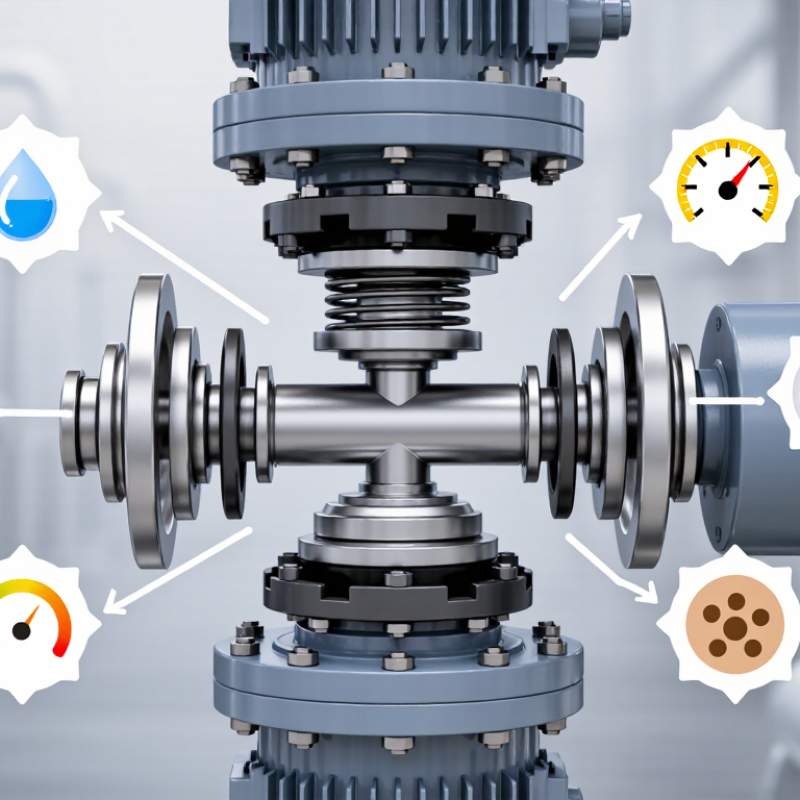
How to Choose a Mechanical Shaft Seal?

Define Pump Duty by Pressure, Temperature, Speed, and Fluid Properties

How to Choose a Mechanical Shaft Seal?

Define pump duty before selecting a seal. Record the highest and lowest suction and discharge pressures, not just normal readings. Include startup pressure, pressure spikes, and the pressure inside the seal chamber. Then log liquid temperature, shaft speed in revolutions per minute, and any changes during cleaning or seasonal operation. Small details matter. A warm flush can change the seal’s environment.

Fluid properties can shift the decision. Note viscosity, solids, abrasiveness, and whether the liquid can vaporize near the seal faces. NIST Chemistry WebBook data puts water’s vapor pressure at about 2.34 kPa absolute at 20°C, rising to about 101.3 kPa at 100°C. That sharp change shows why temperature and chamber pressure must be checked together. API Standard 682 provides a recognized framework for mechanical seals in centrifugal and rotary pumps; use its application categories alongside the actual duty data. A spreadsheet estimate is useful, but it can miss brief pressure peaks. Check instrument logs, and question readings that seem too tidy.

Classify Seal Service Using API 682 Categories 1, 2, and 3

API 682 Categories 1, 2, and 3 define different mechanical seal requirements, not a simple ranking of pump quality. Their exact application depends on the standard edition, pump type, and project specification. Category 1 is generally associated with less demanding process-pump duties, while Categories 2 and 3 bring more specific design and qualification expectations for applicable services. Check the governing edition before treating these categories as interchangeable.

Start with the actual operating conditions. Record seal-chamber pressure, temperature, shaft speed, fluid vapor pressure, and any solids or corrosive components. A hot hydrocarbon that flashes near the seal faces needs different attention from a cool, clean liquid. Consider startup frequency, pressure swings, and leakage controls too. Small details matter. A category label alone cannot capture them.

Match the category to both the pump and the consequence of failure. Confirm whether the pump falls under the applicable API 610 requirements, then review the owner’s seal specification and required test documentation. Category 3 may be appropriate where service demands tighter controls, but it is not automatically the best choice for every installation. Higher requirements can add cost and complexity without solving a poorly understood process problem. I would verify the fluid data and operating envelope with the seal supplier or engineering team before final selection.

Choose API 682 Arrangements 1, 2, or 3 for Leakage Control

How to Choose a Mechanical Shaft Seal?
Choose API 682 Arrangements 1, 2, or 3 for Leakage Control

API 682 Arrangements 1, 2, and 3 are different containment designs, not simple leakage grades. Arrangement 1 uses a single seal, leaving the process fluid as the main containment concern. Arrangement 2 uses two seals with an unpressurized buffer system; leakage can be monitored through that circuit. Arrangement 3 uses a pressurized barrier fluid, typically above seal-chamber pressure, to limit process fluid escaping outward. API 682 provides a useful framework, but it cannot select the arrangement without details such as fluid hazards, operating pressure, temperature, and site support capacity.

The U.S. Department of Energy’s Improving Pumping System Performance sourcebook reports that pumping systems use 25–50% of energy in some industrial operations. That figure concerns entire systems, not seals, but it shows why reliability choices deserve careful review. Arrangement 1 may suit lower-risk services when leakage and maintenance access are acceptable. Arrangement 2 can help where leakage needs monitoring and controlled handling. Arrangement 3 may be appropriate when outward process leakage is unacceptable, provided the barrier fluid is compatible and its pressure remains stable. Details matter. A cloudy sight glass, blocked vent, or drifting instrument can undermine an otherwise sound plan. Real plants are messy, and operating routines should be part of the selection.

Match Seal Faces and Elastomers to Fluid and Temperature

How to Choose a Mechanical Shaft Seal?
Match Seal Faces and Elastomers to Fluid and Temperature

Seal materials must suit the actual fluid, not just its general category. Water with grit can wear faces differently from clean water. Silicon carbide is often considered for abrasive service, while carbon may suit cleaner fluids and provide a forgiving running surface. These are starting points, not guarantees. API Standard 682 treats fluid properties and operating conditions as key seal-selection inputs. Check concentration, solids, pressure, startup temperature, and heat generated at the faces. A seal that works during steady operation may still struggle during frequent starts.

Elastomers need equal care. ASTM D2000 classifies rubber materials by properties including heat resistance, oil resistance, hardness, and tensile strength. It does not make every compound compatible with every fluid. Ask for test data on the exact compound and fluid mixture, especially when temperatures approach the stated limit. Swelling or hardening can compromise secondary sealing. One easy detail to miss: cleaning chemicals or flushing fluid may be more aggressive than the process liquid.

Tips: Confirm temperature at the seal faces, not only the vessel reading. Compare supplier compatibility data with the full fluid composition. When evidence is thin, treat the selection as provisional and test it under representative conditions.

How to Choose a Mechanical Shaft Seal? - Match Seal Faces and Elastomers to Fluid and Temperature
Fluid or Service Typical Seal-Face Pair Possible Secondary-Seal Material Indicative Material Temperature Range Selection Notes
Clean, cool water Carbon graphite / silicon carbide (SiC) EPDM or NBR EPDM: approximately −40 to 150°C; NBR: approximately −30 to 100°C Carbon provides good running-in characteristics in lubricated service. Choose the elastomer based on water temperature and any additives.
Hot water or aqueous service Carbon graphite / SiC, or SiC / SiC for more demanding wear conditions EPDM, subject to grade and water chemistry EPDM compounds commonly cover approximately −40 to 150°C; verify the specific grade for hot water or steam Check pressure, thermal cycling, water treatment chemicals, and the seal design’s operating limits. Elastomer limits alone do not define the seal’s maximum temperature.
Mineral oil, lubricating oil, or fuel Carbon graphite / SiC NBR for many oils; FKM for higher-temperature service when chemically compatible NBR: approximately −30 to 100°C; FKM: approximately −20 to 200°C Compatibility varies with oil formulation, fuel blend, additives, and temperature. Some FKM grades have limited resistance to certain fuels or low temperatures.
Aromatic or chemically aggressive hydrocarbons SiC / SiC, subject to chemical compatibility of the SiC grade FKM or FFKM; confirm compatibility with the exact fluid FKM: approximately −20 to 200°C; FFKM: often approximately −20 to 300°C, depending on grade These are broad guide ranges, not guarantees. Solvent mixtures, concentration, pressure, and exposure time can change compatibility significantly.
Abrasive slurry or water containing solids SiC / SiC; consider a suitable flush or seal arrangement EPDM or FKM, selected for the carrier fluid and temperature EPDM: approximately −40 to 150°C; FKM: approximately −20 to 200°C Hard faces can improve resistance to abrasive wear, but particle size, solids loading, face lubrication, and flushing are critical to service life.
Acidic or alkaline aqueous solution Often SiC / SiC, after checking the specific fluid and material grades EPDM may suit some aqueous chemicals; FKM or FFKM may suit other services Use the selected compound’s published range; typical broad ranges are EPDM −40 to 150°C and FKM −20 to 200°C There is no universally compatible elastomer. Confirm concentration, temperature, and chemical compatibility; some SiC grades and binders may also be unsuitable.

Temperature ranges are approximate reference ranges for common material families. Actual limits depend on compound formulation, pressure, fluid chemistry, shaft speed, heat generation, and seal design. Confirm compatibility and operating limits with material data and the equipment specification before selection.

Select an API 682 Flush Plan, Such as Plans 11, 23, or 32

How to Choose a Mechanical Shaft Seal?
Select an API 682 Flush Plan, Such as Plans 11, 23, or 32

Choosing a flush plan starts with the fluid, operating temperature, and seal-chamber conditions. A plan that works well with a clean, cool liquid may struggle with a hot or contaminated process. Check the pump’s operating range and the seal arrangement before choosing. Small details matter.

Plan 11 sends process fluid from the pump discharge through an orifice and into the seal chamber. It is a common option for suitable, relatively clean services, but the added circulation can bring heat into the chamber. Plan 23 uses a pumping ring and cooler to circulate and cool the fluid locally, making it worth evaluating for hot services. Plan 32 supplies a clean external fluid. Its pressure and compatibility must be carefully controlled; otherwise, process dilution or inadequate flow may create new problems. There is no universal best choice.

Tips: Confirm the actual chamber pressure, fluid temperature, and contamination risk. For Plan 32, verify that flush pressure stays above chamber pressure and that the supply remains reliable. For Plans 11 and 23, consider orifice condition, cooler performance, and maintenance access. A familiar plan can be a tempting shortcut, but it may not suit the actual duty. Review the final setup against the applicable API 682 requirements and pump documentation.