What Are Machined Parts and How Are They Made?
Machined Parts are the quiet foundation of modern products. They appear inside aircraft assemblies, medical instruments, electric motors, and everyday tools. A finished component may look simple, yet its accuracy often depends on careful design, material selection, tooling, and inspection. Manufacturing scholar David A. Dornfeld has noted, “Machining is one of the most energy-intensive processes in manufacturing.” That observation matters because precision involves more than removing metal. It also involves controlling waste, heat, vibration, and dimensional variation.
This guide explains what Machined Parts are and how manufacturers produce them. It follows the process from engineering drawings to cutting, drilling, turning, milling, finishing, and quality checks. A CNC machine may follow digital instructions, but it cannot correct every poor design decision. Not automatically. Skilled technicians still monitor tool wear, surface marks, chips, and unexpected movement during production. A sharp carbide cutter can leave a clean edge on aluminum, while the same setting may damage a harder alloy.
The discussion also considers common materials, tolerances, production volumes, and real-world applications. Some explanations will remain simplified. That is deliberate. Machining depends on many variables, and no single example represents every workshop. Readers should question assumptions, compare specifications, and confirm critical measurements with qualified engineers or inspectors. In practice, reliable Machined Parts come from cooperation between software, machines, materials, and people. Precision begins before the first cut.
What Are Machined Parts?
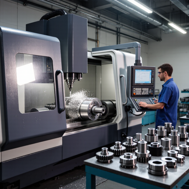
Machined parts are components shaped by removing material from a solid workpiece. Common materials include aluminum, steel, brass, plastics, and titanium. A cutting tool follows programmed paths or controlled manual movements. It creates holes, slots, threads, flat faces, and precise curves. The finished part may look simple, but its accuracy depends on drawings, tool condition, machine stability, and measurement. In practical workshops, even a clean cut can hide a small dimensional error.
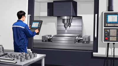
Manufacturing usually starts with a digital model and an engineering drawing. The operator selects stock, secures it, and chooses suitable cutting tools. Milling machines rotate tools against the material, while lathes rotate the workpiece. Drilling and grinding can refine specific surfaces. After machining, inspectors check dimensions with calipers, micrometers, gauges, or coordinate equipment. This verification matters because heat, vibration, and tool wear can change results during a long production run. A perfect first attempt is uncommon.
Tips: Define critical dimensions clearly. Allow sensible tolerances instead of demanding perfection everywhere. Keep sharp edges only where they serve a purpose. Check the material before cutting, because similar-looking metals can behave differently. Record inspection results during production, not only at the end. Small notes often reveal problems earlier.
Which Materials Are Used for Machined Parts?
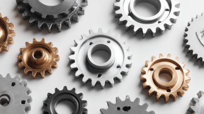
Machined parts are made from solid stock, and the material strongly affects their performance. Aluminum is popular for housings, brackets, and lightweight fixtures. It cuts cleanly and removes heat quickly. Steel suits shafts, gears, and structural components that face heavy loads. Stainless steel resists moisture, chemicals, and staining, but it can generate heat during cutting.
Copper alloys, including brass, work well for fittings and electrical components. Brass machines smoothly and produces a clean surface. Titanium offers high strength with low weight, although it requires careful tooling and slower cutting conditions. Engineering plastics such as nylon, acetal, and PEEK help reduce weight, friction, and electrical conductivity. They can deform if clamped too tightly.
Material selection depends on more than strength. Engineers also check temperature, corrosion exposure, wear, surface finish, and total cost. In a machine shop, operators watch the chips and measure parts during production. Those details often reveal whether the chosen material behaves as expected. Material choice is rarely perfect. A stronger alloy may increase machining time and tool wear. A cheaper plastic may absorb moisture and change size. Designers should compare technical data with real operating conditions. Small trials can prevent expensive failures, especially when tight tolerances or thin walls are involved.
How Are Machined Parts Designed and Prepared?
Designing machined parts starts with function, not the drawing screen. Engineers define loads, motion, material, and service temperature before selecting dimensions. A practical design also considers cutter access, tool diameter, workholding, datum surfaces, and chip evacuation. Internal corners need realistic radii because standard tools cannot cut perfectly sharp edges. Deep pockets often require longer tools, which can increase vibration and reduce accuracy.
The 2024 World Robotics report recorded 4,281,585 industrial robots operating worldwide in 2023. This growth makes machine-ready design increasingly important. Clean CAD geometry helps, but it does not guarantee a stable process. Designers should export verified models, apply clear geometric tolerances, and identify critical surfaces for inspection. CAM programmers then choose cutting strategies, speeds, feeds, and stock allowances. Simulation can reveal collisions before metal reaches the spindle. Small mistakes remain expensive.
Preparation should include a process sheet, setup sequence, fixture concept, inspection method, and material certificate. According to the U.S. Energy Information Administration’s Manufacturing Energy Consumption Survey, manufacturing remains a significant industrial energy user. Efficient toolpaths and fewer setups can reduce both cycle time and waste. I have found that simple datum schemes often outperform complicated ones. Yet this is not universal. A lightweight part may distort during clamping, even when its CAD model looks perfect. Engineers should review first-article results, question unexpected tool wear, and revise the design when production evidence disagrees with assumptions.
What Steps Are Involved in Machining?
Machining begins with a careful review of the part drawing. The machinist checks dimensions, tolerances, material, surface finish, and required features. A steel block, for example, may need holes, slots, and curved edges. Each feature affects the cutting order.
The workpiece is then selected and secured in a vise, chuck, or fixture. Correct alignment matters. A small setup error can spread across every dimension. The machinist loads cutting tools and enters tool paths from the approved digital model. Speeds and feed rates depend on the material, tool type, and cut depth.
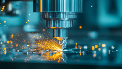
Cutting usually starts with roughing, which removes excess material quickly. Finishing passes create accurate surfaces and sharper details. Coolant may reduce heat and extend tool life. Measurements are taken with calipers, micrometers, gauges, or a coordinate measuring machine. The first pass is rarely perfect. Tool wear, vibration, and thermal movement can change results. Experienced machinists watch for unusual sounds and fresh marks on the surface. After machining, edges are deburred, cleaned, and inspected against the drawing. Inspection records should identify actual measurements, not assumptions. A second review is worthwhile when tolerances are tight.
How Are Machined Parts Inspected and Finished?
Machined parts are inspected through a controlled sequence, not a quick visual check. Technicians verify dimensions with calipers, micrometers, gauges, and coordinate measuring machines. Critical features may be checked at several temperatures because thermal expansion can affect results. ISO 14253 recommends evaluating measurement uncertainty before accepting a dimensional decision. The 2023 ISO Survey recorded more than 1.5 million ISO 9001 certificates worldwide. This figure reflects the continuing need for documented quality systems and traceable inspection records.
Surface finishing follows inspection priorities. Deburring removes sharp edges and loose chips. Anodizing, plating, passivation, polishing, or coating may then improve corrosion resistance and appearance. Surface roughness is measured with a profilometer, often against a drawing requirement such as Ra 1.6 μm. ASME Y14.5 practices help inspectors interpret tolerances and geometric controls consistently. Still, a perfect report cannot repair poor process control. That is an uncomfortable weakness.
Tips: Confirm the drawing revision before measurement. Clean the part and instruments first. Record temperature, tool identity, operator, and measured values. Use calibrated equipment with an unexpired certificate. For tight tolerances, request a measurement system analysis, such as a gauge repeatability and reproducibility study. Do not polish a surface before checking its original condition. Finishing can hide tool marks, alter dimensions, or remove evidence of machining problems. Photograph unusual defects, but never replace numerical records with photographs alone.
What Are Machined Parts and How Are They Made?
Machined parts are components shaped by removing material with cutting tools. The chart shows typical dimensional tolerance ranges commonly associated with major machining processes. Final inspection may use calipers, micrometers, gauges, or coordinate measuring machines, while finishing operations such as grinding, deburring, polishing, anodizing, or plating improve surface quality and protection. Actual results depend on material, machine condition, tool selection, geometry, and production requirements.